Hardware Manual
Revision: 1.8
Copyright © 2003-2021 Smart Avionics Ltd.
19/09/2021
- 1. Introduction
- 2. Preparing for Propeller Balancing
- 3. Preparing for Rotor Balancing
- 4. The PB-4 User Interface
- 5. Upgrading the PB-4's Firmware
- A. Battery Charging & Replacement
- B. Specifications
- C. EMC Compliance & Safety Information
- D. CE Declaration of Conformity
- E. UKCA Declaration of Conformity
- Index
- 1.1. Wi-Fi roles when PB-4 is in AP mode
- 1.2. Wi-Fi roles when PB-4 is in STA mode
- 1.3. PB-4 panel
- 2.1. Accelerometer axes and orientation
- 2.2. Accelerometer mounted on a Rotax 912 gearbox
- 2.3. Tacho sensor with flexible mounting plate
- 2.4. Tacho sensor mounted on cowling
- 2.5. Tacho sensor angle of incidence
- 2.6. Cable taping
- 3.1. Standard sensor orientation (top view)
- 3.2. Sensors mounted on an MTO rotor head (rear-right view)
- 3.3. Sensors mounted on a Magni prerotator drive
- 3.4. Sensors mounted on an AutoGyro Mk2 rotor head (front-left view)
- 3.5. Sensors mounted on an AutoGyro Mk2 rotor head (rear view)
- 3.6. Sensors mounted on an AutoGyro Mk2 rotor head (left view)
- 3.7. Exploded view of the AutoGyro Mk 2 rotor head sensor mount
- 3.8. Tacho shining onto reflective tape attached to prerotator disk
- 4.1. Initial screen
- A.1. Locating the PB-4 board securing screws
- A.2. Correct orientation of RTC battery
This manual describes the hardware of the Smart Avionics PB-4 product and how to prepare for balancing a propeller or rotor using the PB-4. The balancing procedures and the features of the PB-4 software are covered in the user interface manual (pb4_ui_manual.pdf).
The PB-4 balancing system has these main components:
| Accelerometer | This is mounted near the hub of the propeller/rotor to detect the vibration due to imbalance. |
| Optical tachometer | A strip of reflective tape is attached to one propeller/rotor blade and an optical sensor detects the tape as it passes and generates the tachometer signal required by the balancer. |
| Digital processor (CPU) | This processes the vibration signal and sends the resulting data over a Wi-Fi network to be displayed on the user interface (UI) device. |
| User interface device | This provides the means whereby the user can view the results and interact with the PB-4 using a standard web browser. The PB-4 may also be used with the Propeller Balancer Android app. |
The PB-4 uses Wi-Fi to communicate with the user interface device which can be any computer that supports a modern browser and Wi-Fi. Obviously, the most suitable devices for use in aircraft are lightweight tablets. A 7" format tablet is a good choice for use while balancing as it is not too bulky but still has reasonable screen resolution. Later, you can look at the results on a device with a bigger screen, e.g. a laptop computer. The following text simply calls the user interface device a tablet.
The PB-4 uses a Wi-Fi network to communicate. Most commonly, a Wi-Fi network consists of an access point and one or more stations. The network traffic to and from the stations is routed through the access point. The PB-4 can operate as either a Wi-Fi station or as a Wi-Fi access point depending on where you are located at the time.
When you are at the airfield doing the balancing, you would not normally have an access point available. Fortunately, the PB-4 can be the access point (as well as being a balancer). By starting the PB-4 in AP mode, it will be an access point and the tablet will be able to communicate with it directly as shown below. Note that unless the tablet has some other means of accessing the internet, it will only be able to talk to the PB-4 in this configuration.

When you are back indoors, your tablet will most likely be already configured to use an existing access point at that location. The PB-4 can be started as a station (STA mode) and it will then use the same access point as the tablet so they will be able to communicate. In this configuration, your tablet will be able to access the network (internet, printers, etc.) as normal.

For the PB-4 to be able to talk to the access point, it needs to know the access point's SSID (Wi-Fi network name) and password. The PB-4 supports Wi-Fi Protected Setup (WPS) which makes setting up the access point credentials easy. The SSID and password may also be entered into the PB-4 manually if required.
![[Note]](images/note.svg) | |
One way of remembering which mode you need to use is that when you are "at the AirPort" use AP mode and when you "STAy at home", use STA mode! |
Safari users please note that the PB-4 is not compatible with Safari's “Private Mode”.
Accessing the PB-4 user interface from your tablet's browser requires the PB-4 and the tablet to be using the same Wi-Fi network.
When the PB-4 is in AP mode, the Wi-Fi network name (SSID) will be PB4-XX where XX are two letters/digits. You will need to tell your tablet to use that Wi-Fi network (via its Wi-Fi configuration). At the airfield, the tablet will probably use the PB-4 Wi-Fi automatically because your normal Wi-Fi is not available. If not, you will have to tell the tablet to use the PB-4 Wi-Fi manually.
Once the tablet is using the PB-4 network, you can load the user interface page into the browser. If your tablet supports MDNS, you can simply use pb4.local as the host name in the browser. Apple devices (mac/ipad/iphone) and most Linux systems have MDNS, most Windows systems do not. If not, use the IP address 172.21.21.1. Having accessed the PB-4 user interface page, just add a bookmark for that page in your browser called something like "PB-4 AP Mode (at the airfield)".
When the PB-4 is in STA mode, the Wi-Fi network name (SSID) will be whatever you normally use at the current location. The PB-4 will need to be taught that SSID and the associated password. The PB-4 supports WPS for automatically obtaining the SSID and password from the access point which is quick and easy if the access point also supports this feature. Alternatively, you can manually enter the credentials by starting the PB-4 in AP mode, loading the user interface into your browser (as described above), connecting to the PB-4 (click on red button) and then going to Menu / Options / PB-4 Configuration / Set Access Point Details.
Once the PB-4 is able to connect to the local network, you can load the user interface page into the tablet's browser. Again, if MDNS is supported by the tablet, the host name pb4.local can be used. Otherwise, you need to find out the IP address that has been assigned to the PB-4 by the access point. Follow these steps:
Turn on the PB-4 in STA mode (press the on/off switch until LED 2 goes green). When you release the switch, LED 2 will go off and then after a few seconds will flash green slowly if the PB-4 has successfully managed to log into the access point.
Turn the PB-4 off (press switch until the LEDs go out).
Turn the PB-4 on again but this time start it in AP mode (press on/off only until LED 1 comes on).
Access the PB-4 user interface page with your browser as described in the previous section, connect to the PB-4 (click on red button) and then go to Menu / About. The about box will contain a line that says STA Mode IP Address: XX.XX.XX.XX. The address that is shown is the IP address that has been assigned to the PB-4 by the access point, note it down.
Having found out the PB-4's IP address when in STA mode, you can use that address to access the user interface page and then add a bookmark for that page in your browser called something like "PB-4 STA Mode (at home)".
The PB-4 is powered by 4 x 1.2V AA NiMH rechargeable batteries. The batteries are easily accessible via a hatch in the bottom of the PB-4 case. The PB-4 itself cannot charge the batteries, they have to be removed and charged in an external charger. It is also possible to use non-rechargeable 1.5V AA batteries in the PB-4.
The PB-4 also contains a CR2032 3V coin cell which provides backup power. This battery will require replacing every now and then.
See Appendix A, Battery Charging & Replacement for more information on battery charging and replacement.

The panel contains:
Please operate the PB-4 within the following environmental limits:
| Temperature | -20° to +45° C (-4° to 113° F) |
| Relative humidity | 5% to 95% non-condensing |
![[Warning]](images/warning.svg)
![[Caution]](images/caution.svg) | |
Propellers can kill. Make sure that the ignition is switched off before touching the propeller. Always assume that the engine could fire when the propeller is being moved. Make sure that the aircraft is securely chocked or tied down while carrying out the balancing process. |
To carry out the balancing process, you will need the following items in addition to the balancer kit:
Balance weights (typically AN970 washers) and a means of securely attaching them to the spinner backplate.
If necessary, a bracket for mounting the accelerometer onto the front of the engine (optional, depending on engine type and installation details). An M6 screw and washer are supplied which can be used to attach the accelerometer to the back of a Rotax 4-stroke gearbox if the vacuum pump option is not fitted.
The following points should be observed regarding positioning the aircraft for a propeller balancing session:
The position must be safe for ground running of the engine. Typically, the engine will need to be run at cruise RPM and the aircraft should be braked and chocked and, if necessary, tied down.
If the sun is low on the horizon it is best if the sun does not lie within the arc of the propeller when viewed from the location of the tacho sensor.
If there is any wind, point the aircraft as close into wind as possible while observing point 2 above. If the wind is greater than 10kts or gusty it will be difficult to obtain a really good balance.
Remove sufficient cowlings to gain access to the front of the engine. Mount the accelerometer (40mm square with a 6mm hole through the middle) as near to the front of the engine as possible with the accelerometer's sensing axis pointing directly at the propeller's centre line.
The accelerometer's X axis coincides with the direction of the sensor's cable socket and its Y axis is at 90° to the direction of the cable socket.

![[Important]](images/important.svg) | |
The sensing axis used must intersect the axis of rotation of the propeller. Remember to configure the job to use the correct axis. |
Note that the accelerometer does not have to be directly above the propeller's axis of rotation. However, to get the best results you should not mount the accelerometer such that the sensing axis is parallel with the engine's cylinders.
On a Rotax 4-stroke engine that doesn't have a vacuum pump attached, the best place to mount the accelerometer is on the rear of the gearbox using one of the available tapped holes and the supplied M6 screw and washer.

If the accelerometer cannot be bolted directly to the engine, some form of bracket will be required. Obviously, the details of this are engine specific but it could be as simple as a strip of metal with a hole drilled at each end. If a bracket is used, it must be sufficiently stiff to ensure that the accelerometer does not move with respect to the engine.
However the accelerometer is mounted, it must not be subjected to excessive temperatures. The temperature of the sensor should not exceed 85° C. If necessary, thermally insulating material can be sandwiched between the accelerometer and the engine (or bracket) to reduce the amount of heat conducted to the accelerometer. If the surrounding area will be very hot, the accelerometer could be wrapped in thermally insulating material (once the cable has been attached).
| |
The accelerometer is robust but may be damaged if dropped on a hard surface. |
It is preferable to refit the engine cowling to minimise the turbulence generated by the airflow from the propeller. For some aircraft, the cowling will have to be refitted to provide a suitable mounting position for the optical sensor. However, if the balance weights are to be added to the rear of the spinner backplate, it may pay to leave the cowling off (if possible) during the balancing process so that it is easier to gain access to the weights. Once the balancing has been completed, the cowling could be replaced and a final reading taken to determine the level of vibration achieved.
Owing to the variation in aircraft cowling shapes and sizes, only generic instructions can be provided here. You may find that a little experimentation is required to obtain the best results.
The tacho sensor is drilled for a 6mm fastener and so it may be securely bolted to the airframe using a suitable bracket. With an adequately strong bracket, it would be safe for the aircraft to be flown with the sensor attached in this way (assuming no other safety issues arise).
For ground use only, a flexible plastic mounting plate is provided. The sensor is bolted to the plate and then the plate may be taped to the aircraft cowling. The supplied soft washer should be placed between the tacho sensor and the mounting plate to increase the friction as this will reduce the fastener torque required.
| |
This method of mounting the tacho sensor on the cowling is perfectly adequate when the aircraft is stationary on the ground. Under no circumstances should the aircraft be flown with the tacho sensor attached using the flexible mounting plate. |
| |
If the propeller is a pusher, i.e. the cowling is in front of the propeller rather than behind, extra care should be taken to ensure that the tacho sensor cannot become detached from the cowling and hit the propeller blades. As a minimum, tape the accelerometer cable to the cowling so that it will restrain the tacho sensor in the event of it becoming detached from the cowling. If you have any doubt as to the security of the tacho sensor, don't risk destroying it and the propeller. |
Position the tacho sensor such that the sensor block is pointing towards the propeller. If the sensor's orientation is correct, the blades will sweep across the sensor block as the propeller rotates. The distance from the front of the sensor to the propeller should be in the range 5-75cm.

Figure 2.4, “Tacho sensor mounted on cowling” shows the tacho sensor mounted an aircraft cowling.
| |
To detect the propeller RPM reliably when the propeller blades are reflective, the tacho sensor should be positioned such that the angle of the LED beam is not normal to the faces of the propeller blade. Rotate the tacho sensor so that it is approximately 30° from the normal (either in front of or behind the normal). Figure 2.5, “Tacho sensor angle of incidence” illustrates this. If the angle is too small, the tacho sensor will tend to detect the other blades (especially if they are highly reflective) and the RPM will appear erratically too high. If the angle is too large, the blade with the reflective tape will not be reliably detected and the RPM will appear zero or erratically too low. |

With the engine ignition switched off, rotate the propeller so that one blade lies directly on the sensing axis of the tacho sensor. Make sure that the area on the back of the blade where the tape is going to be attached is clean. Apply a strip of 25mm wide masking tape to the back of the propeller at the point that the red beam will hit the blade. Wrap the tape a short distance around the leading edge of the blade but don't wrap it around the trailing edge.
| |
The tape must be oriented such that it is parallel to the tacho sensor's body. This ensures that as the blade sweeps across the tacho sensor, the maximum length of reflective tape will be seen by the sensor. This may mean that the tape is not at 90° to the leading edge of the blade but that doesn't matter. |
Now put a strip of the reflective tape on top of the masking tape, it should extend to close to the leading edge but not actually wrap around the leading edge.
If you subsequently find that the tacho sensor cannot reliably detect the RPM, verify that the tape really is in the correct position. You may find that adding another strip of reflective tape next to the first strip will improve the situation.
![[Tip]](images/tip.svg) | |
When the tacho sensor is connected and the PB-4 is powered up and connected to the tablet, the red LED will flash regularly. If the tacho sensor is receiving a large amount of reflected light, the LED will stop flashing. To check that the sensor is correctly orientated, move the propeller so that the tacho sensor's beam is pointing at the most reflective portion of the background (but not the tape). If the LED is continuously on, rotate the sensor until the LED starts flashing. Check that the tape still passes through the LED beam. |
Connect the accelerometer and tacho sensor to the PB-4 using the supplied cables (4 pin connectors for the accelerometer and 3 pin connectors for the tacho sensor). Make sure the connectors' retaining collars are screwed down (take care to only rotate the metal retaining collar and not the plastic body of the connector).
Any slack in the cables should be taken up by coiling the cable and then applying a few strategically placed pieces of masking tape to stop the cable flapping around in the propeller breeze.

If you tape the cables as shown in the above figure, they are unlikely to come adrift.
| |
To obtain the best results, the cables should be kept away from sources of electrical interference such as ignition leads, magnetos/ignition units, generators/alternators/regulators and their associated wiring. Be especially careful to ensure that the cable cannot get close to rotating components or very hot surfaces. |
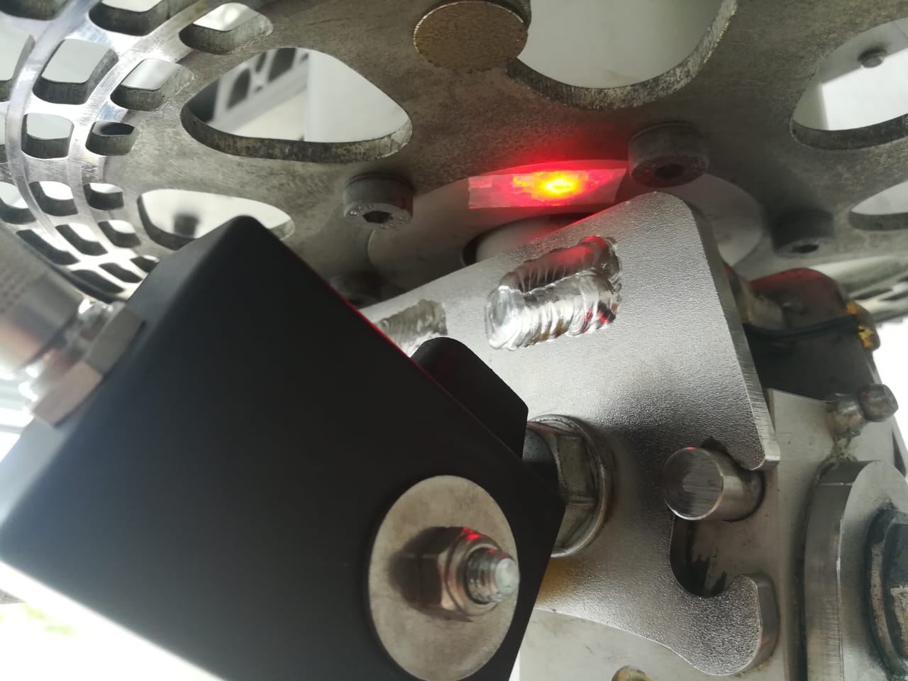
For gyroplane rotor balancing, the accelerometer and the tacho sensor must be mounted on the rotor head using one or more brackets. Exactly how this is achieved is dependent on the design of the rotor head. A common configuration (e.g. for AutoGyro & ELA gyros) is to position the reflective tape on the underside of the prerotator disk with the tacho sensor mounted below the disk. Another common configuration (e.g. for Magni gyros) is to mount the sensors aft of the mast with the reflective tape attached to the slave rotor blade. However the sensors are mounted, you must ensure that the reflective tape is always aligned with the beam from the tacho sensor whatever the position of the rotor head. i.e. moving the aircraft's control stick should not affect the alignment.
The following general points should be observed:
The figures below show both sensors mounted together, they can also be mounted separately, if desired.
The bracket(s) need to be sufficiently sturdy to take the weight of the sensors and to not resonate at any frequency less than 2 times the max rotor RPM.
The accelerometer must be securely mounted such that at least one of its sensing axes passes through (or close to) the rotor's axis of rotation and that sensing axis is also parallel to the rotor disk (this is the horizontal axis).
If you want to measure the vibration in the vertical direction, the other accelerometer sensing axis should be normal (90°) to the rotor disk.
The tacho sensor must be securely mounted such that the distance between the LED and the reflective tape is between 2cm and 75cm. A distance of 10cm to 30cm (4" to 12") works best. The supplied soft washer should be placed between the tacho sensor and the mount to increase the friction as this will reduce the fastener torque required.
If the background itself is reflective (light coloured paint or metal, especially if the surface is rough), the tacho sensor should be rotated so that the light beam strikes the reflective tape at an angle from the normal. The closer the LED is to the reflective tape, the more the sensor will need to be rotated. For short distances and highly reflective backgrounds, the sensor may need to be rotated at least 45° to minimise the spurious reflections from the background.
When the tacho sensor is connected and the PB-4 is powered up and connected to the tablet, the red LED will flash regularly. If the tacho sensor is receiving a large amount of reflected light, the LED will stop flashing. To check that the sensor is correctly orientated, move the rotor so that the tacho sensor's beam is pointing at the most reflective portion of the background (but not the tape). If the LED is continuously on, rotate the sensor until the LED starts flashing. Check that the tape still passes through the LED beam.
The cables from the accelerometer and the tacho sensor must be securely attached to the rotor mast (e.g with cable ties) such that they cannot interfere with any part of the cyclic control or prerotator mechanisms.
The standard accelerometer orientation advocated by Smart Avionics is to point the X axis to the right (when viewed from above) and point the Y axis forward.

The PB-4 is supplied with sensor mounts for popular gyro types, they are described below.
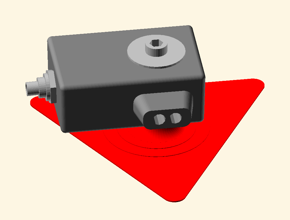
This mount is fastened to the right hand side of the rotorhead. It is compatible with ELA and early AutoGyro (MTO) rotorheads. The accelerometer is orientated such that the X axis is pointing to the right of the machine and the Y axis is pointing forward. Note that the tacho sensor has been rotated to approximately 30° from the normal to avoid spurious reflections from the prerotator disk.
| |
The reflective tape is attached to the bottom of the prerotator disk with the master blade in the 12 o'clock position. |
| |
Use one of the |

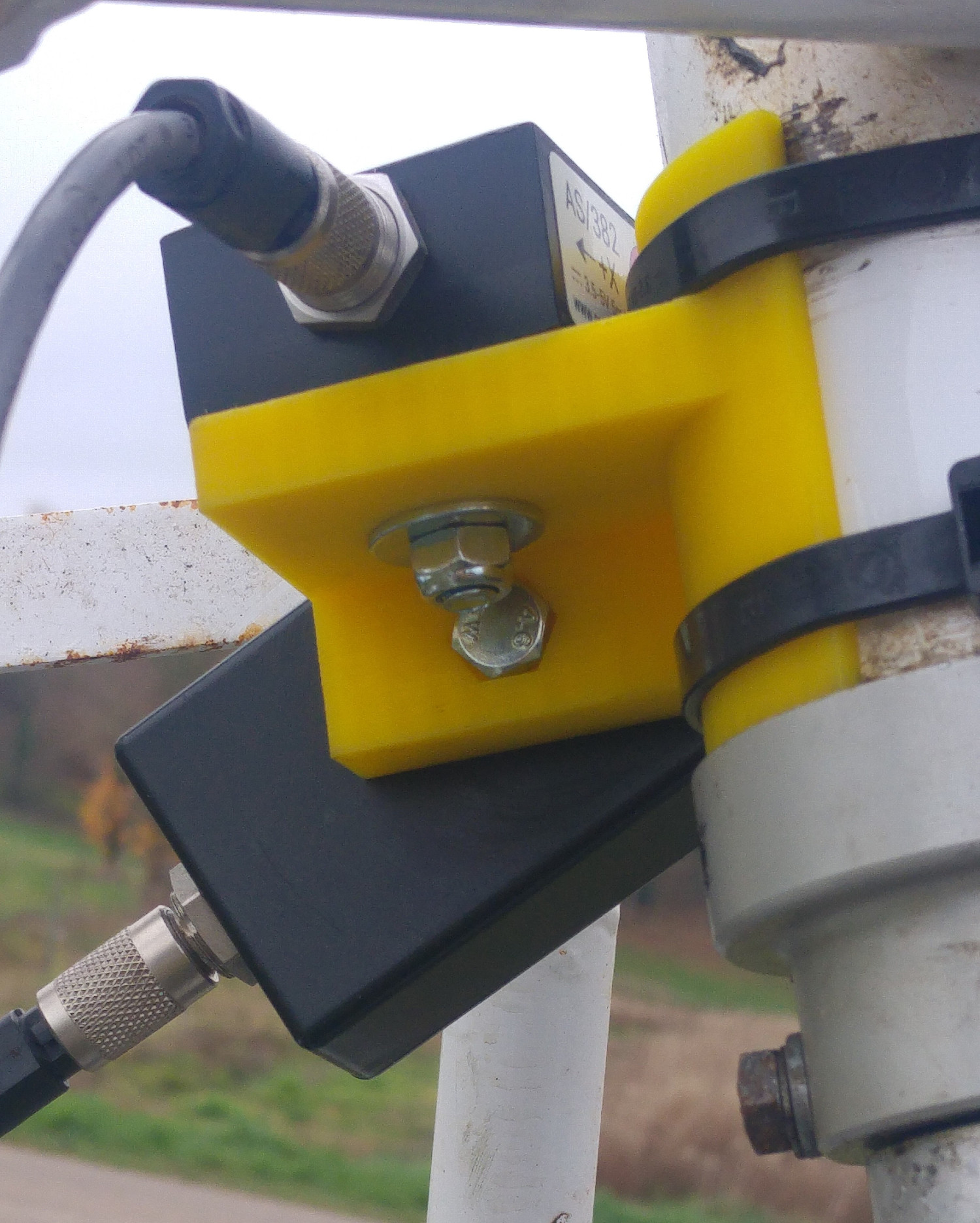
This mount is used with Magni gyroplanes. It is strapped to the rear of the prerotator drive. The accelerometer is orientated such that the X axis is pointing to the right of the machine and the Y axis is pointing forward.
| |
The reflective tape must be attached to the bottom of the slave blade. |
| |
Use either the |
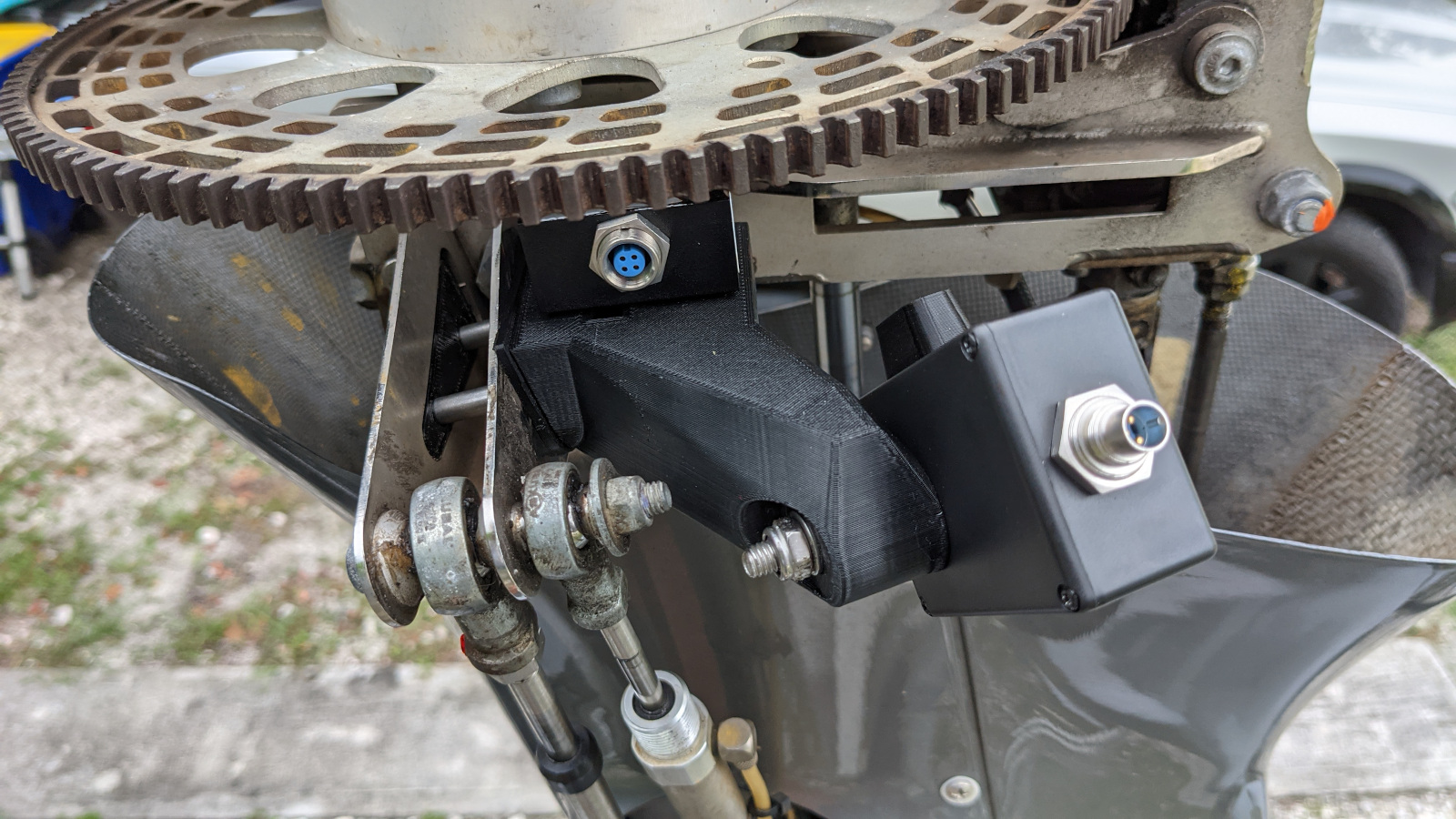
This mount is used for AutoGyro gyroplanes fitted with the Mk2 rotor head. The accelerometer is orientated such that the X axis is pointing to the left of the machine and the Y axis is pointing rearward. This is different from the standard accelerometer orientation described above but as long as the correct rotor profile (AutoGyro-RH2) is used, all will be OK.
| |
The reflective tape must be attached to either the bottom of the slave blade or to the bottom of the prerotator disk immediately below the slave blade. |
| |
Use the |


This sensor mount is attached to the AutoGyro Mk 2 rotor head using two 50mm M6 cap screws.
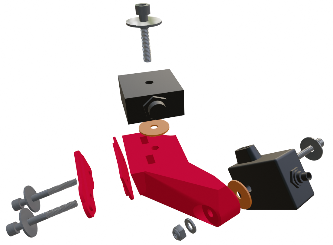
Use soft washers between the sensors and the mount to increase the friction so that less fastener torque is required.
When using the ELA / AutoGyro mount, the tape is attached to the bottom of the prerotator disk.
When using the Magni mount, the tape is attached to the bottom of the slave blade.
When using the AutoGyro Mk2 mount, you have the option of attaching the tape to either the bottom of the slave blade or the bottom of the prerotator disk.
A simple procedure for positioning the reflective tape is:
If you are not using the AutoGyro Mk2 mount, place the master blade at the 12 o'clock position (pointing forward when looking from above).
If you are using the AutoGyro Mk2 mount, position the slave blade immediately above the tacho.
Turn on the PB-4 so that the tacho light is shining on the part to be tracked during rotation (adjust the angle of the tacho as required).
Attach the reflective tape to the centre of the area the tacho light is illuminating (having degreased that area first).
The PB-4 enclosure must be constrained so that it cannot become loose in flight. Preferably, it will be located inside the aircraft's cockpit where it could be held (but not by the pilot!) or tucked into a pocket, etc. If it is to be mounted outside of the cockpit, it must be securely attached to a properly designed and constructed mount.
| |
It is the operator's responsibility to ensure that the PB-4 enclosure is safely constrained and that it cannot become a flight hazard. |
| |
When the sensors, cabling and PB-4 have been installed, verify that the normal range of movement of the rotor head is still available and that the cables cannot become tangled in the controls, engine or propeller. |
The PB-4 kit includes a push button with cable that can be plugged in the PB-4's jack socket. Pressing the push button will capture a polar point and/or a spectrum even if the tablet is not connected to the PB-4. This means that you can capture data simply with the push button without even taking the tablet flying. The capture button is equipped with a velcro strap which can be used to attach it to the control stick or some other convenient location.
Please see the user interface manual for details of how the offline capture button is configured and enabled.
The PB-4 actually supports two completely separate user interfaces:
- Web Browser
The PB-4's primary user interface is browser based and it should be usable on any system that provides a web browser that supports recent web standards. All browsers have quirks so you may find that the PB-4 user interface performs better (or worse!) when you use a different browser.
- Android App
Recent versions (version 3.1 onwards) of the Propeller Balancer App that Smart Avionics provides for use with the PB-3 can also be used with the PB-4. To use the PB-4, in the Propeller Balance App go to Preferences / Data Source and select PB-4. The next time the App is started, it will look for a PB-4 rather than a PB-3. See the Propeller Balancer App manual for further information.
Just a few words here to get you started. When you load the PB-4 user interface into your browser, it will display a splash screen for a few seconds and then show an initial screen similar to Figure 4.1, “Initial screen”.

This shows a polar chart and a list of captured points (both empty as no points have been captured yet). At the top of the screen, a couple of important buttons are displayed along with the name of the current job. The buttons are:
| Menu Button | This pops up a menu that lets you choose various actions. |
| Connect / Disconnect Button | This button toggles the connection to the PB-4. When connected, the button becomes green and the text changes to display the PB-4 battery level. When you are actually collecting data (points/spectra) or when you are configuring the PB-4, you will need to be connected. If you are just looking at the data for the current job, you do not need to be connected. |
For the full description of how to use the PB-4 browser based user interface, please go to Menu / Help.
The PB-4 user interface is "responsive" - the layout changes depending on the resolution and orientation of the user interface's screen. It should be usable on many different user interface devices. For lower resolution devices, you may find that changing the orientation to landscape is beneficial.
The PB-4 software is partitioned into 3 parts (UI, CPU and Wi-Fi), each of which may be upgraded separately by uploading the appropriate file to the PB-4.
| |
Before upgrading any of the firmware, ensure that the PB-4's battery level is adequate (20% or more). The upgrade procedures do not take more than a couple of minutes. |
| |
Unfortunately for ipad/iphone owners, iOS (the system used by ipads/iphones) does not support uploading files via the browser so you will need to use a laptop or PC to carry out the upgrades[1]. |
The UI firmware consists of the web files (HTML, CSS, Javascript) that are loaded into the tablet's browser. New UI firmware will be packaged as a file named pb4ui-version.zip.
To install new UI firmware, load the PB-4 UI into a browser and then go to Menu / Options / Upload UI Files where you can select the zip file to upload. The contents of the zip file will be uploaded to the PB-4 and the next time you load the UI into your browser, you will be using the new files.
In the unlikely event of this procedure failing and rendering the unit unusable, please contact Smart Avionics for instructions on how to recover.
The PB-4 CPU firmware is responsible for digitising the vibration signals, calculating the IPS/DEG values, doing the spectral analysis, storing the results, etc. New CPU firmware will be packaged as a file named pb4-version.fw.
To install new CPU firmware, load the PB-4 UI into a browser, connect to the PB-4 and then go to Menu / Options / PB-4 Configuration / Upload PB-4 CPU Firmware where you can select the .fw file to upload. The contents of the .fw file will be uploaded to the PB-4 and the unit will restart and then program the CPU with the new firmware. Do not turn the PB-4 off while this is being done! When the programming has finished, LED 1 should flash green quickly. Press the on/off switch and the PB-4 will turn off. Next time you turn it on, the new firmware will be used.
In the unlikely event of this procedure failing, LED 1 will flash red quickly. Press the on/off switch and the PB-4 will turn off. Because the update failed, the PB-4 will revert to using the firmware that was installed when it was made. You can retry the procedure and if it fails again, please contact Smart Avionics for advice.
The Wi-Fi Firmware is installed into the PB-4's Wi-Fi module. New Wi-Fi firmware will be packaged as a file named wifi-date.dfu.
To install new Wi-Fi firmware, load the PB-4 UI into a browser, connect to the PB-4 and then go to Menu / Options / PB-4 Configuration / Upload PB-4 Wi-Fi Firmware where you can select the .dfu file to upload. The contents of the .dfu file will be uploaded to the PB-4 and the Wi-Fi module will be programmed with the new firmware. Do not turn the PB-4 off while this is being done! When the programming has finished, LED 1 should flash green quickly. Press the on/off switch and the PB-4 will continue.
In the unlikely event of this procedure failing, LED 1 will flash red quickly. Press the on/off switch and the PB-4 will continue. Because the update failed, the PB-4 may now not be accessible via the Wi-Fi. If that happens, it is likely that the unit will need to be returned to Smart Avionics to be made usable again.
The PB-4 is powered by 4 x 1.2V AA size batteries. It is supplied with high quality NiMH batteries that can be recharged over 2000 times. Furthermore, these batteries self discharge very slowly and so the batteries will remain charged for a long time when the PB-4 is not in use. It is recommended that the batteries are charged using an intelligent battery charger at a 500mA rate. Please follow the instructions supplied with the battery charger.
It is also possible to use other brands of battery and even non-rechargable AA batteries if that's all that is available. If you are using different batteries, the battery level indicator will probably not be correct as it is calibrated for the supplied batteries but the unit will keep running until the batteries are exhausted even if the battery level indicator reaches zero.
The PB-4 also contains a CR2032 3V coin cell which powers the unit's Real Time Clock (RTC) when the PB-4 is powered down. Very occasionally, this will need replacing and a message will appear on the UI when the battery needs to be changed. To do that, carry out the steps below.
| |
When handling the PB-4's circuit board, avoid generating static electricity (don't walk about, brush your hair, stroke the cat, etc!) Hold the board by the metal sensor connectors and the edges. |
Remove the AA batteries from the battery compartment.
Remove the 4 screws that hold the case halves together and separate the top from the bottom.
Remove the battery connector from the circuit board (flat connector with red/black wires).
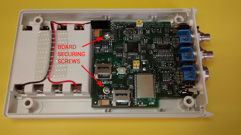
Undo the two screws that hold the circuit board in the case (see Figure A.1, “Locating the PB-4 board securing screws”).
Remove the circuit board along with the front panel from the case.
The battery is contained in a holder on the underside of the board, push the old battery out of the holder using a non-metalic item.
Insert the new battery fully into the holder ensuring that the + sign on the battery is towards you and away from the board (see Figure A.2, “Correct orientation of RTC battery”).
Replace the board in the case and fasten it in place with the two screws.
Reconnect the battery connector (it is not polarised so can go either way round).
Reassemble the case halves and replace the 4 screws.
Replace the AA batteries.
Safely dispose of the old CR2032 battery in accordance with your local regulations.

| Wi-Fi standard | 2.4GHz IEEE 802.11 b/g/n |
| Required user interface | Web standards compliant browser supporting HTML5, CSS, Javascript and WebSockets. |
| Balancing RPM range | 100-13,000 RPM |
| Tachometer channels | 2 |
| Accelerometer channels | 2 x dual-axis |
| Spectrum display RPM range | 100-25,500 RPM (100 RPM per spectral line) |
| Spectrum (FFT) Windows | None, Hann, Flat Top |
| Battery life (1900 mAh) | approx 8 hours |
| Dimensions | 163mm × 95mm × 33mm |
| Weight | 330 grams |
| RPM Range | 0 to 25,000 RPM |
| Acceleration Range | Nominal ± 5.36 G |
| Supply Voltage | 3.5V to 5V at 5 mA |
| Output Signal | Analogue |
| Dimensions | 46mm (plus cable and connector) × 40mm × 20mm |
| Weight | 60 grams |
| Mounting Hole | M6 |
| Sensor To Tape Distance | 1cm to 100cm (under ideal conditions) |
| RPM Range | 60 to >100000 RPM |
| Supply Voltage | 3.5V to 5V at 60 mA |
| Output Signal | One pulse per revolution with the rising edge synchronised to the centre of the tape |
| Dimensions | 63mm (plus cable and connector) × 55mm × 24mm |
| Weight | 85 grams |
| Mounting Hole | M6 |
To ensure EMC compliance, please observe the following conditions when using the PB-4:
Do not use the PB-4 in close proximity to other electrical equipment capable of generating large amounts of electrical interference.
All electrical equipment in the aircraft that is not required for either safety reasons or to facilitate the running of the engine should be switched off while the PB-4 is being used.
As described in this manual, avoid routing the PB-4's cables near to sources of electrical interference (such as engine ignition components and cabling).
Only use cables approved by Smart Avionics for connecting the sensors to the PB-4.
To satisfy FCC RF exposure limit compliance, the PB-4's Wi-Fi transmitter must not be co-located or operated in conjunction with any other antenna or transmitter.
The following safety statements should be observed:
The protection provided by the unit will be impaired if it is used in a manner not specified by the manufacturer.
We, Smart Avionics Ltd. Chorlton Lane Farm, Chorlton, Malpas, Cheshire. SY14 7ES. United Kingdom, declare, on our own responsibility, that the PB-4 conforms with the essential requirements of the Radio Equipment Directive 2014/53/EU.
Conformity is declared to the following harmonised standards:
- EMC
EN61326-1:2013 “Electrical equipment for measurement, control and laboratory use - EMC Requirements”.
- RF
EN 300328 V1.8.1 “Electromagnetic compatibility and Radio spectrum Matters (ERM); wideband transmission systems; Data transmission equipment operating in the 2.4 GHz ISM band and using wideband modulation techniques”.
- Safety
IEC 61010-1:2010 (3rd edition) and EN 61010-1:2010 “Safety requirements for electrical equipment for measurement, control and laboratory use”.
Equipment type: Battery powered portable test/measurement.
Environment: External/Workshop.
I, the undersigned, hereby declare that the PB-4 conforms to the above Directive.

Mark Burton
Director
Smart Avionics Ltd.
11 July 2016
We, Smart Avionics Ltd. Chorlton Lane Farm, Chorlton, Malpas, Cheshire. SY14 7ES. United Kingdom, declare, on our own responsibility, that the PB-4 conforms with the essential requirements of the Radio Equipment Directive 2014/53/EU.
Conformity is declared to the following harmonised standards:
- EMC
EN61326-1:2013 “Electrical equipment for measurement, control and laboratory use - EMC Requirements”.
- RF
EN 300328 V1.8.1 “Electromagnetic compatibility and Radio spectrum Matters (ERM); wideband transmission systems; Data transmission equipment operating in the 2.4 GHz ISM band and using wideband modulation techniques”.
- Safety
IEC 61010-1:2010 (3rd edition) and EN 61010-1:2010 “Safety requirements for electrical equipment for measurement, control and laboratory use”.
Equipment type: Battery powered portable test/measurement.
Environment: External/Workshop.
I, the undersigned, hereby declare that the PB-4 conforms to the above Directive.
Mark Burton
Director
Smart Avionics Ltd.
7 January 2021
A
- accelerometer
- mounting, Mounting the accelerometer, Mounting the sensors
- mounting bracket, Mounting the accelerometer
- sensing axes, Mounting the accelerometer
- temperature, Mounting the accelerometer
- aircraft
- positioning, Positioning the aircraft
B
- balance
- weights, Additional items required
- batteries, Batteries, Battery Charging & Replacement
C
- cables, Attaching the cables
- capture
- offline button, Offline capture button
- connect
F
- factory reset, PB-4 panel
- firmware
- upgrading, Upgrading the PB-4's Firmware
G
- gyroplane rotor, Mounting the sensors
O
- on-off switch, PB-4 panel
P
- PB-4
- positioning, Positioning the PB-4, Positioning the PB-4
R
- reflective tape, Attaching the reflective tape, Mounting the sensors
T
- tacho sensor
U
- User Interface, The PB-4 User Interface
W
- Wi-Fi
- access point, Wi-Fi network components
- station, Wi-Fi network components
- wind, Positioning the aircraft
- WPS
- invoking, PB-4 panel